Description
Sound and light control switch instructions
Circuit function
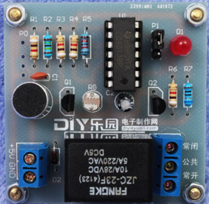
1) Voice control switch function: Cover the photo resistor RG. A clap will turns on the light, and another clap will turns off the light. Set the jumper cap P1 on the two pins. The normally open end and common end of the relay are used as switches to connect to the bulb.
2) Touch switch function: Cover the photo resistor RG. Touch the P terminal light to turn on, and touch the P terminal light to turn off. Set the jumper cap P1 on the upper two pins. The normally open end and common end of the relay are used as switches to connect to the bulb.
3) Voice control delay function: Cover the photo resistor RG. The lights turn on with a clap. The lights turn off automatically after a while. Set the jumper P1 on the normally open end, the relay are used as switches to connect to the light bulb. The delay time can be changed by changing the size of C2.
4) Touch delay function: Cover the photo resistor RG. Touch the P terminal to turn on the light. The light will turn off automatically after a while. Set the jumper P1 on the lower two pins. The normally and common ends of the relay connects to the light bulb. The delay time can be changed by changing the size of C2.
5) Light control function: The voice control and touch function must work when the circuit is in dark (at night).. If the photor esistor is removed, it can be worked in day and night.
6) If the signal of the sensor is input from pin 3 of CD4013, it can be used in a variety of applications. For example, connect a magnetic tube to the ground and pin 3 of CD4013, and remove the transistor Q1. It forms a magnetic control switch.

