Description
Circuit principle
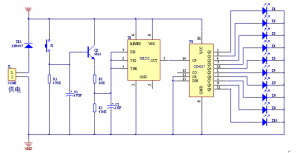
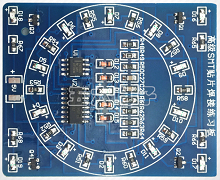
The circuit is mainly composed of a pulse generator and a decimal counter circuit. The pulse generator is composed of NE555 and peripheral components to form a multivibrator. When the button sw is pressed, VT1 is turned on, and the 3 pins of NE555 output pulses, then the 10 output terminals of CD4017 output high level in turn to drive 10 LEDs to emit light in turn. After releasing the button, due to the presence of capacitor C2, VT1 will not be cut off immediately. As the voltage across C2 drops, the conduction process of VT1 gradually weakens, the frequency of the output pulse of pin 3 slows down, and the movement frequency of the LED also follows. Slow down. Finally, after the discharge of C2 is over. VT1 ends. The 3 pins of NE555 no longer output pulses, and the LED stops moving. The process of a “lottery draw” is thus completed. R2 determines the moving speed of the LED and C2 determines the time to wait for the “lottery”.
