Description
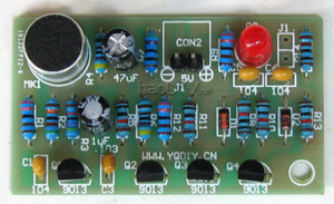
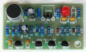
Q1 and Q2 form a secondary audio amplifier circuit. The audio signal received by MK1 is coupled to the base of Q1 via C1. After amplification, the collector is directly fed to the base of Q2. A negative square wave is obtained at the collector of Q2. To trigger the bistable circuit. R1 and C1 limit the frequency response of the circuit to around 3kHz, which is a high sensitivity range. When the power is turned on, the state of the bistable circuit is that Q4 is off, Q3 is saturated, and D3 is off. When MK1 receives the control signal, it outputs a negative square wave after two-stage amplification. After differential processing, the negative sharp pulse is added to the base of Q3 through D1, causing the circuit to flip quickly and D3 is lit. When MK1 receives the control signal again, the circuit flips again and D3 goes out. The circuit board is reserved with terminal J1 for connecting external control equipment, which can be used to connect relays through J1 for voice control of other equipment. (When connecting the relay, a diode must be reversed at both ends of the relay coil)
